2023-03-13
What Are the 3 Basic Parts of a Universal Joint?

When you think of a car, the first thing that comes to mind is probably the engine. But what about all the other parts that work together to make the car run? One of those important but often overlooked parts is the universal joint. Let's take a closer look at what are the 3 basic parts of a universal joint and how they work.
What Is a Universal Joint?
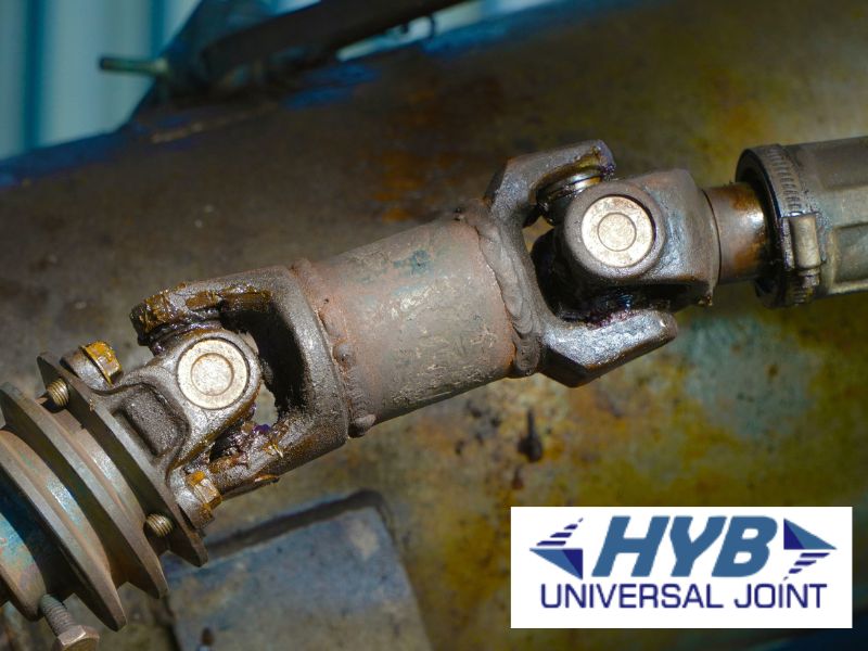
A universal joint is a type of coupling that connects two shafts that are at different angles to each other. It allows for free rotation in any direction around its axis. The most common name of the universal joint is the Cardan joint, named after its inventor Gerolamo Cardano.
Unlike other couplings, the universal joint can transmit rotational power even when the two shafts are not perfectly aligned. This makes it ideal for use in automotive applications with a lot of vibration and movement.
3 Basic Parts of a Universal Joint
Universal joints have three key components:
- Driving yoke
The driving yoke is part of the universal joint that connects to the power source, such as an engine.
- Driven yoke
The driven yoke is part of the universal joint that connects to the load, such as a wheelset.
- Spider
An intermediary connects the yokes on a mechanical cross called the spider. The shaft in the spider can be rotated at various angles. If the input shaft is attached directly to the spider, it will rotate the cross, turning the output shaft.
How do Universal Joints Parts Connect?
This section will cover how the three parts of the universal joint are connected with different scenarios.
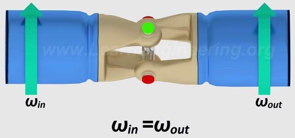
1. The Shafts Connected Straight

In the first scenario, the input and output shafts are connected in a direct line. This makes things quite simple. The input shaft will rotate the cross, which as a result, rotates the output shaft. You can see that both the input and output shafts will turn at matching speeds.
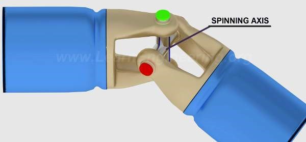
2. Shafts Are at an Angle - The Spin of the Cross
The movement is very different when the shafts are at an angle. If you take notice of the red and green ends on the cross, you'll see that the green ends (connected to the input shaft) rotate along a vertical plane, whereas the red ends (connected to the output shaft) have to shift horizontally.

The cross has to spin along the axis connecting the green ends so that the red ends move across the inclined plane. If you look closely at the mark on the cross, you can see this in action.
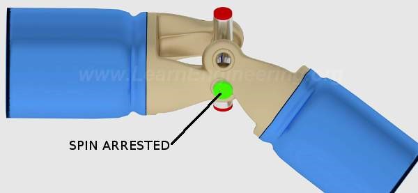
To make the cross-spin concept more understandable, pretend that the green axis spin has stopped. This motion is shown in the image below.

The motion of the inclined hook joint can't occur without this spin.
How Double Universal Joint Works?
Sometimes there are scenarios where a single universal joint cannot be used, and that is where a double universal joint comes into play. A double universal joint has two sets of bearings connected by a cross-shaped member. This allows the shaft to be connected at two points rather than one.
The jerky rotation makes the original universal joint dysfunctional. However, you can turn it into a constant velocity joint by adding one more joint, as depicted. A constant velocity input will cause fluctuating output, whereas a fluctuating input results in constant velocity output. Therefore, the double universal joint functions as a constant velocity joint. A similar arrangement can be seen in rear-wheel-driven automobiles. It is evident that the drive shaft is placed between two universal joints, thus, resulting in an output speed at the second universal joint that equals the input speed.
Structure Of Universal Joint
The universal joint, which allows for the transmission of ample torque at a low friction rate, consists of a spider and four bearings filled with grease. The journal pegs and bearing cases act as outer rings; they are hot-forged or cold-formed before machining. Afterward, they are carburized in a furnace to make them more resistant to wear and tear.
The spider is a forged or cast part that has two Trunnions. It also features a groove where the circlip is placed to secure the ball bearings. The spider is placed in between the two yokes and functions as an intermediary that connects them.
Applications of Universal Joints
The universal joint is an important component of many types of machinery. It is used in the automotive industry for the drive shafts of four-wheel drive vehicles. It is also used in construction, agricultural machinery, and many other industrial machineries.
The universal joint allows two shafts to be connected at an angle while still allowing the shafts to rotate freely. This means that the universal joint can be used in a wide variety of applications where two shafts need to be connected at an angle.
Main Functions of a Universal Joint
There are three main functions of a universal joint:
1. To join two separate shafts together at the point where their axles intersect.
2. To allow two shafts to rotate independently about their own axes.
3. They allow for transmitting power while the angle constantly changes, not only at a set angle.
Final Thoughts
U-joints are one of your car's or truck's most important parts and are often taken for granted. Without them, your vehicle wouldn't be able to turn smoothly and efficiently. It's essential to be familiar with the different types of u-joints so that you can make an informed decision when it comes time to replace them.
